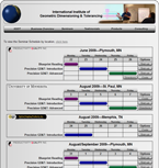
GD&T Seminar Series
|
April 22-26, Salt Lake City, Utah
May 3-7,
Minneapolis, Minnesota |
|
| GD&T Seminars |
 |
|
IIGDT has developed a multi-step Geometric
Dimensioning and Tolerancing Seminar Series built upon
years of proven experience in training new users in the
fundamental to advanced topics of GD&T. Whether you are
new, or an experienced user of GD&T, there is a Seminar
level designed for you.
|
|
Click here to visit the GD&T Seminar home page |
|
Precision GD&T and Requirements for
Software Validation |
|
The precision language of Dimensioning & Tolerancing is explicitly defined in the ASME Y14.5M-1994 Standard on Dimensioning and Tolerancing, and is mathematically complimented by the ASME Y14.5.1M-1994 Standard on Mathematical Definition of Dimensioning and Tolerancing Principles. Both of these Standards form the basis for a precise definition of complex surface geometries and should be the basis for mathematical analysis using validated software intended to be in compliance with “FDA 21 CFR PART 11.” |
|
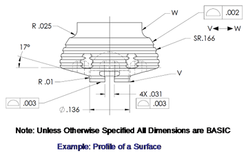
3D Engineering Drawing Example
utilizing Profile of a Surface |
 |
 |
|
|
|
| Case study for the application of Profile |
|
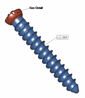
The availability of advanced CAD design tools and
manufacturing capabilities often incorporate complex,
blended shapes. These surfaces are not easily defined by
the prismatic shapes that we have grown accustomed too
and requires an offset profile band, or halo surrounding
the CAD model.
Test Criteria for
Compliance to Engineering Requirements
Stated Compliance to the engineering requirements as
defined per the ASME Y14.5 and Y14.5.1 Standards and
therefore FDA 21 CFR PART 11 require compliance with the
following “Test Criteria.”
-
Size, which is
defined as having two parts based on “Limits of Size”
criteria defined in section 2.3 of the Y14.5.1 Standard.
This requires compliance to both the “Actual Local Size”
and “Actual Mating Size.”
- Datums which are
based on criteria defined in section 4.3 of the Y14.5.1
Standard which requires:
- Datum “Features of
Size at RFS” (Regardless of Feature Size) to be
simulated as “Actual Mating Envelopes.”
- Datum
“Features of Size at MMC (Maximum Material Condition) or
LMC (Least Material Condition)” to be simulated as
“Virtual Conditions.”
-
“Multiple Features of Size”
defined as a “Single Datum” to be “Simulated as
Patterns” based on “Actual Mating Envelopes” (RFS) or
“Virtual Conditions” (MMC or LMC).
- Position
Tolerances which are based on criteria defined in
section 5 of the Y14.5.1 Standard which requires:
- Analysis of axes based on “Actual Mating Envelope”
principle.
- Analysis of “Bonus Tolerance” based on
applicable features defined at MMC or LMC.
- Analysis of “Simultaneous Requirement” which requires
all features to simultaneously be within their
respective tolerances when the feature control frames
have the same datum, in the same sequence with the same
datum feature modifiers.
-
Analysis of
Single-Segment -vs- Composite Feature Control Frames.
- Profile Tolerances which are based on criteria
defined in section 6.5 of the Y14.5.1 Standard which
requires:
- Minimum Zone fitting algorithms are
used.
- Profile results must always look for the
smallest possible deviation of the actual geometry
(worst case measured point) from nominal geometry,
ideally a CAD model that can be compared to the profile
tolerancing in the feature control frame.
-
Must
ensure “Simultaneous Requirements” are being met which
requires all features to simultaneously be within their
respective tolerances when the feature control frames
(Single-Segment) “have the same datum, in the same
sequence with the same datum feature modifiers.”
- Revision changes of software must be validated to
original “Test Criteria” for continued “Proof of
Compliance” to ensure ongoing integrity of measured
results and conformance to requirements.
|
|
|
| IIGDT Seminars |
IIGDT offers 6 levels of training courses to suite your
business requirements. These are:
|
|
|
|
| |
| Announcements: |
To see our complete schedule please visit the Seminar page,
click here:
|
 |
| |
| |
| |
| |
|
Dr. Hetland discusses the critical challenges facing today’s medical OEMs and suppliers
in validating analytical software used for determining
compliance to mechanical drawings for components and
assemblies. This article will make visible some of the risks
and limitations in current software validation and provide
direction to simplify future validation initiatives. click here. |
 |
| BONEZONE
Archives |
| |
|