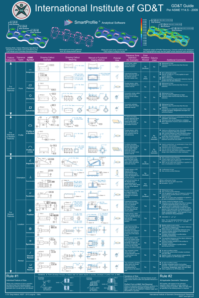
 IIGDT has released a new GD&T Symbol Chart supporting the ASME Y14.5-2009 standard. Since the original chart was issued based on the 1994 standard several changes have been implemented. In addition, the IIGDT chart provides clear and descriptive explanations for all symbols. IIGDT has released a new GD&T Symbol Chart supporting the ASME Y14.5-2009 standard. Since the original chart was issued based on the 1994 standard several changes have been implemented. In addition, the IIGDT chart provides clear and descriptive explanations for all symbols.
New for this year is the expanded use of 3D profile shown being applied to CAD models to demonstrate the effective use and interpretation of Profile call-outs.
Each symbol is presented with a visual explanation for:
- Drawing Callout Example
- Drawing Callout Meaning
- Manual or Functional Gaging Method
- Pictorial View
Each GD&T Symbol also is described for:
- Tolerance Zone Definition
- Zone Modifiers Allowed
- Datums Used
- Additional Comments
Developed by Dr. Greg Hetland, this guide has been widely used in industry and can be found in many companies across the world.
Size: 24" (610 mm) x 36" (914 mm)
A Poster Paints a Thousand Words... Read about the History of the Chart here.
Visit the GD&T ASME Y14.5-2009 Chart on iigdt.com
|


