| Do you have machinsts that feel they produce holes in parts correctly to engineering requirements but the inspectors provides feedback to the machinist, in the form of a reject tag, that the part does not conform? Is it possible they’re making completely different measurements and providing completely different results, yet both confident the measurements they’re taking are correct? The only thing they might be confident in is that their respective measurement results are repeatably and reproducibly different, both without truly knowing if their individual results conform to the engineering standard the drawing states compliance to? For example, does the engineering drawing state “Unless Otherwise Specified Dimensioning & Tolerancing per ASME Y14.5-2009? If so then neither the machinist or inspector might be measuring the simple hole correctly.
Machinists potentially measure size of a hole using a 2-point bore gage while the inspector measures the same hole with a 3-point bore gage. Are they truly measuring size correctly per the applicable ASME Y14.5 standard? Inspectors might also measure the hole the same as the machinist, which might mean they’re both measuring it wrong, or the inspector might be using a 2D vision system or 3D tactile measuring system, both with a small or large number of measuring points. However, with any coordinate measuring system the question would be: is the inspector using the default algorithm within the coordinate measuring system (CMS), which in most cases would be considered an average diameter (many times referred to as “best-fit” or Gaussian least-squares).
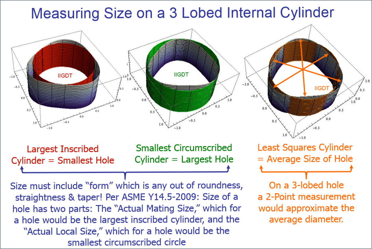
The definition of size per the ASME Y14.5-2009 Standard, size of a hole has two parts: The “Actual Mating Size,” which for a hole would be the largest inscribed cylinder, and the “Actual Local Size,” which for a hole would be the smallest circumscribed circle. What this means is that size includes “form” which is any out of roundness, straightness & taper, so depending on the lobing condition of the hole (2 lobe versus 3 lobe or other), that neither a 2-point or 3-point measuring instrument is capable of directly measuring the hole for size.
If however they know the magnitude of the form and the specific lobing condition they could jointly determine the more optimal measuring instrument and could also determine the magnitude of guard-banding they would need to do to the specification to determine the modified specification limits they could use to ensure the holes truly conform to the original engineering requirements.
|